
Reliable and timely communication between several controllers is crucial to modern embedded systems. Devices in robotics, automotive electronics, industrial automation, and medical equipment need to communicate data fast and precisely. The Controller Area Network (CAN) protocol becomes crucial in this situation. Originally created for automotive networks, Robert Bosch GmbH’s CAN is today extensively utilized in numerous embedded applications.
It eliminates the requirement for a host computer by enabling communication between several microcontrollers via a common bus. CAN is perfect for real-time control systems because it is reliable, fault-tolerant, and effective in noisy electrical situations. FITA Academy offers industry-focused Embedded Systems Training that covers microcontrollers, C programming, hardware interfacing, real-time systems, and IoT fundamentals. Let’s look at some clear, achievable steps to help you understand embedded systems and develop practical skills for real-world electronics and automation projects. Engineers have a significant advantage when they know how to apply CAN in embedded systems, particularly in the automotive and industrial sectors. Let’s examine how to incorporate CAN into your embedded projects step-by-step.
Understanding the Basics of CAN Protocol
CAN is a message-based communication protocol that uses a multi-master architecture. This means any node on the network can initiate communication when the bus is free. Data is transmitted in frames that include an identifier, control bits, data bytes, and error-checking fields. The identifier determines message priority through a process called arbitration. During arbitration, the message with the highest priority (lowest ID number) wins access to the bus without data collision. CAN also includes built-in error detection mechanisms such as cyclic redundancy check (CRC), acknowledgment checks, and bit monitoring. These features make CAN highly reliable in harsh environments. The protocol typically operates at speeds up to 1 Mbps in standard CAN and even higher in CAN FD variants. This structured and efficient communication method makes CAN perfect for real-time embedded applications.
Key Hardware Components Required
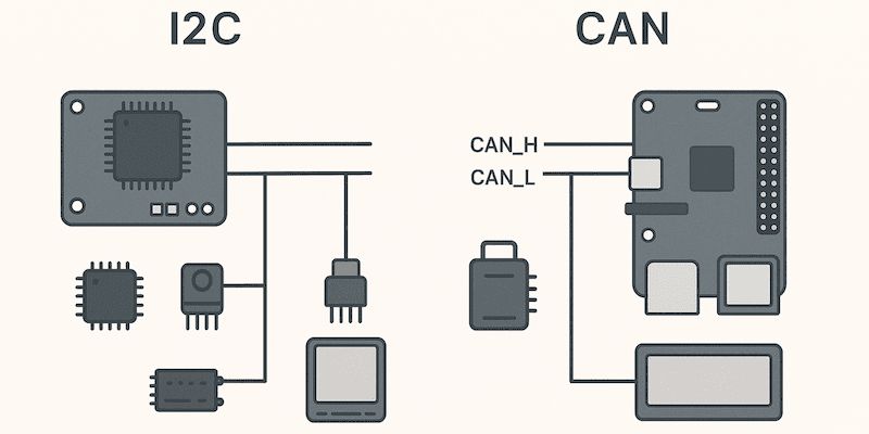
Certain hardware components are required in order to implement CAN in an embedded system. First, pick a microcontroller that has a CAN controller module integrated into it. CAN is supported by a large number of ARM Cortex-M microcontrollers. A CAN transceiver, which transforms logic-level CAN signals into differential signals appropriate for the CAN bus, is then required. Models of transceivers that comply with ISO 11898 specifications are popular.
Embedded System Courses in Chennai offer comprehensive training in microcontrollers, C programming, hardware interfacing, real-time systems, and IoT applications with hands-on projects and expert mentoring. To stop signal reflections, termination resistors (usually 120 ohms) must be added to both ends of the CAN bus. Communication mistakes rise dramatically in the absence of appropriate termination. CAN_H and CAN_L are the two lines used by the CAN bus. In electrically loud environments, these differential lines provide dependable communication and enhance noise immunity. Selecting compatible hardware minimizes integration problems later in development and guarantees reliable connection.
Step-by-Step CAN Setup in an Embedded Project
To learn CAN peripheral configuration, start by choosing a microcontroller and reading its datasheet. In the microcontroller’s system setup, turn on the CAN clock. Next, set up GPIO pins for the transmit (TX) and receive (RX) operations of CAN. Set the CAN peripheral’s initial baud rate according to your network’s specifications. Configure message filters so that only pertinent message IDs are accepted.
Attach the CAN transceiver between the CAN bus lines and the microcontroller. Make that the termination resistor and grounding are positioned correctly. Power the system and check the voltage levels on CAN_H and CAN_L after the hardware connections are finished. Now that the physical layer is prepared, you can move on to evaluating the communication at the software level.
Configuring CAN Registers and Initialization
Proper register configuration is necessary for CAN communication. Configure the bit timing register to specify the time segments, baud rate prescaler, and synchronization jump width. Precise timing guarantees accurate signal interpretation by all nodes. To enable regular working mode, set up the CAN control register. To determine which message identifiers the node should receive, use filter registers.
In order to manage message transmission and reception events, many microcontrollers also have interrupt enable registers. Enrolling in an Embedded Systems program at a B School in Chennai can significantly boost your career readiness and employability by strengthening your knowledge of microcontrollers, C programming, hardware interfacing, real-time systems, and IoT applications, while enhancing your practical skills through hands-on projects and industry-oriented training. Effective initialization guarantees seamless message exchange and avoids communication breakdowns. Because mismatched settings result in communication issues, always double-check the baud rate uniformity across all network nodes.
Writing Embedded C Code for CAN Communication
Write embedded C code to send and receive CAN messages after configuration is finished. The message ID and data bytes must be loaded into the transmit mailbox register in order to send data. Make a transmission request and watch for interruptions or status indicators to confirm it. Keep an eye on the receive FIFO register for messages. Read the message’s identity and data bytes upon receipt, then clear the receive flag. In real-time systems, interruptions are more efficient than polling. Separate the initialization, transmission, and receiving routines to create a modular code structure. Code that is well-structured facilitates debugging and increases system maintainability.
Testing and Debugging CAN Communication
When using CAN, testing is essential. To track message flow and confirm proper transmission, use a CAN analyzer tool. The CAN_H and CAN_L lines’ differential voltage signals can be examined using oscilloscopes. Verify the appropriate voltage levels, which are normally between 2.5V idle and differential signaling while transmitting. We should know the main component of embedded system. Check the grounding connections and termination resistors first if communication is lost. To find problems like bit errors or acknowledgment failures, keep an eye on the error counters in CAN status registers. Debugging efficiently guarantees system dependability prior to deployment and reduces development time.
Common Challenges and Troubleshooting
Developers frequently encounter problems such as wrong termination, inappropriate baud rate setup, or wiring errors. If shielding is insufficient, communication may also be impacted by noise interference. Misconfigured message filtering, which stops nodes from receiving legitimate frames, is another frequent issue. Prior to making any changes to software, always confirm the physical connections. Before expanding to larger networks, begin with two nodes and conduct gradual testing. Root causes can be promptly found by examining error codes and maintaining firmware logs. Structured troubleshooting guarantees that communication issues are resolved more quickly.
Real-World Applications of CAN Protocol
Automotive networks are dominated by the CAN protocol, which links infotainment modules, airbags, braking systems, and engine control units. CAN is used in industrial automation systems for sensor integration and machine control. For motor controller communication, robotics platforms rely on CAN. The dependability of CAN in real-time data interchange is advantageous for medical equipment as well. It is a reliable communication protocol in safety-critical industries due to its resilience and error-handling features. Career options in industrial embedded development and automotive electronics are made possible by learning CAN implementation.
Best Practices for Reliable CAN Implementation
Ensure that all nodes have the same baud rates. Reduce noise interference by using appropriate shielding and grounding procedures. Put error-handling procedures in place in the firmware to control retransmissions and bus-off states. To preserve signal integrity, keep wiring lengths within advised bounds. To guarantee stability, test communication often under various load scenarios. Network configurations should be documented for simpler upkeep. Adhering to these recommended practices guarantees effective CAN network performance and enhances long-term system stability.
End suggestion
Careful hardware selection, appropriate configuration, organized code, and extensive testing are necessary for CAN protocol implementation in embedded systems. You can create dependable communication networks for practical applications by comprehending CAN architecture, effectively configuring hardware, and producing effective embedded C code. You will be able to incorporate CAN into automotive, industrial, and Internet of Things embedded systems with confidence if you practice and have debugging experience.